


Forklift Fork Capacity Chart: Width, Thickness, and Load Center Explained
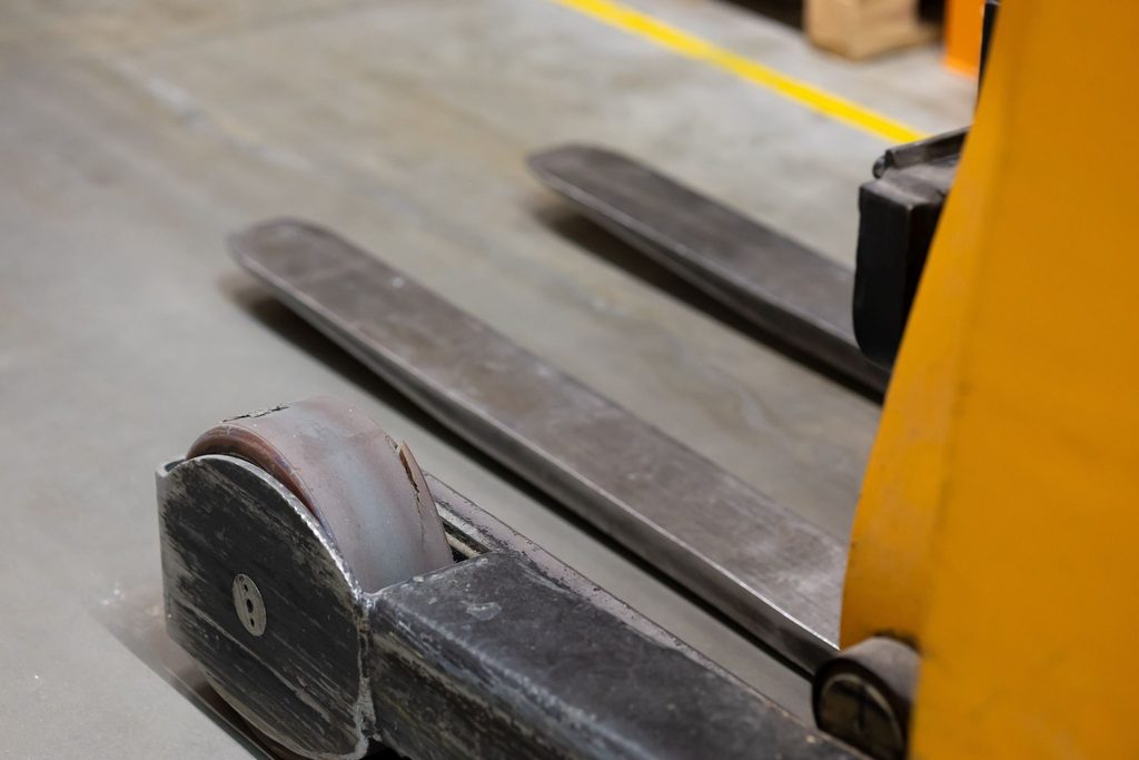
In material handling, understanding lift capacity is one of the most critical factors for facility safety and equipment longevity. While fleet managers and operators typically know the rated lifting limit displayed on their forklift’s data plate, forks carry their own independent load capacities and dimensional engineering limits.
Matching your lift truck to the correct fork arms requires understanding three foundational variables: blade width, blade thickness, and load center distance. If these specifications fail to align with your application, you risk fork failure, load loss, and severe safety violations.
What Determines Forklift Fork Capacity?
A forklift fork operates as a horizontal cantilever beam supported at the vertical carriage. When a load is placed on the blade, bending stress concentrates at the heel—the 90-degree radius transition where the vertical shank meets the horizontal blade.
A fork’s structural capacity depends primarily on:
- Blade Cross-Section (Width × Thickness): The volume of heat-treated alloy steel resisting bending moment stresses.
- Load Center Distance: The horizontal distance from the front face of the shank to the payload’s center of gravity.
- Carriage Class (ITA Mounting Standard): The mechanical hook spacing connecting the arm to the truck carriage.
- Heel Integrity: The remaining thickness of the heel relative to the original shank profile.
Forklift Fork Capacity Reference Chart
Below is a general reference chart for standard hook-type ITA fork arm pairs at a standard 24-inch (600 mm) load center. Capacities represent matched pairs made from high-strength, fully heat-treated alloy steel.
| Carriage Class | Hook Distance | Common Fork Dimensions (Width × Thickness) | Rated Capacity / Pair (@ 24″ Load Center) | Typical Truck Capacity Range |
| Class II | ~16 inches | 4″ × 1.5″ (100 × 40 mm) | 4,000 – 5,000 lbs | 2,000 – 5,500 lbs |
| Class II | ~16 inches | 4″ × 1.75″ (100 × 45 mm) | 5,000 – 5,500 lbs | 2,000 – 5,500 lbs |
| Class II | ~16 inches | 5″ × 1.75″ (125 × 45 mm) | 5,500 – 6,000 lbs | 2,000 – 5,500 lbs |
| Class III | ~19–20 inches | 5″ × 2.0″ (125 × 50 mm) | 6,000 – 8,000 lbs | 5,500 – 10,000 lbs |
| Class III | ~19–20 inches | 6″ × 2.0″ (150 × 50 mm) | 8,500 – 10,000 lbs | 5,500 – 10,000 lbs |
| Class IV | ~23.5–25 inches | 6″ × 2.5″ (150 × 60 mm) | 12,000 – 15,000 lbs | 10,000 – 17,500 lbs |
| Class IV | ~23.5–25 inches | 7″ × 2.75″ (175 × 70 mm) | 15,000 – 17,500 lbs | 10,000 – 17,500 lbs |
(Note: Always verify fork stamping and equipment data plates before moving maximum loads. Never exceed the lower rating between the truck, the carriage, and the fork pair.)
Width vs. Thickness: Why Cross-Section Matters
When operators evaluate fork arms, they often prioritize blade width to increase surface contact with pallets. However, thickness plays a far greater role in lifting capacity.
In structural beam mechanics, resistance to bending is governed by the section modulus (S), where:
S = (w × t²) / 6
(where w is blade width and t is blade thickness).
Doubling the width of a fork arm doubles its strength (2), but doubling the thickness quadruples it (4). Thickness provides the primary vertical stiffness needed to hold heavy weights without excessive deflection or metal fatigue.
The 10% Heel Wear Rule
Because thickness provides structural resistance, normal abrasive wear against concrete floors is a primary safety concern. As forklifts slide under pallets, the bottom of the heel wears down over time.
Under ITA and OSHA standards:
- A 10% reduction in fork blade thickness reduces load capacity by 20%.
- Once 10% wear occurs at the heel, the fork must be removed from service immediately.
To ensure an accurate assessment, always measure blade thickness on the vertical shank or un-abraded heel area rather than at the tapered tip. For step-by-step instructions on measuring blade geometry, consult the guide on How to Measure Forklift Arms.
Load Center Explained: The Leverage Principle
A fork rating is only valid at a specified load center—the horizontal distance from the front face of the shank to the payload’s center of gravity.
For standard North American GMA pallets (48″ × 40″), the load center is usually 24 inches (the midpoint of a uniform 48-inch depth). If a load is oversized, oddly shaped, or picked up with the tips, the center of gravity moves forward.
This creates a longer lever arm, increasing the bending moment at the heel:
Effective Capacity = Rated Capacity × (Rated Load Center / Actual Load Center)
Practical Impact on Capacity
If you pick up a long crate with a 36-inch load center using forks rated for 5,000 lbs at 24 inches:
Effective Capacity = 5,000 lbs × (24 in / 36 in) = 3,333 lbs
Operating past the rated load center reduces load stability, over-stresses the fork heel, and risks tipping the forklift truck forward.
How to Read Fork Stampings and Identification
Manufacturers mechanically stamp fork specifications onto the vertical shank, typically on the side or rear between the upper and lower hooks.
A standard stamp includes:
- Rated Capacity: E.g., 2500 x 24 (2,500 lbs capacity at a 24-inch load center per fork) or 5000 / PAIR (combined capacity).
- Dimensions: Often shown in millimeters or inches (e.g., 45 x 100 x 1200 for thickness, width, and length).
- Mounting Class & Part ID: Denoting carriage class compatibility (Class II, III, or IV).
- Serial Number: Provides manufacturing batch traceability, steel alloy origin, and heat-treatment certification.
If your fork markings are obscured by paint, rust, or grease, clean the shank with a wire brush or non-corrosive degreaser—never grind into the metal, as removing steel weakens the arm. Learn more about identifying stamped ratings in our resource on How to Read Fork Markings.
Choosing the Right Fork for Your Application
Selecting the proper fork requires balancing load requirements, carriage mounting, and blade profile:
- Standard ITA Hook-Type Forks: The standard choice for warehousing, 3PL logistics, and manufacturing handling standard wooden pallets.
- Fully Tapered & Polished (FTP) Forks: Engineered with a thin profile tapering continuously from shank to tip. Ideal for slip sheets, drywall/gypsum board, lumber stacks, and low-clearance entries where standard blunt tips would snag or damage goods.
- Block & Lumber Forks: Built with wider profiles and reinforced shanks to handle unpalletized masonry, concrete blocks, and broad bundles of raw lumber without flexing.
For detailed application recommendations across standard and specialized hook-mount equipment, read our complete breakdown on Choosing the Right Fork.
Quality Forks for Safer Material Handling
Using properly rated, undamaged fork arms protects your operators, prevents inventory damage, and maintains regulatory compliance. Whether you are replacing standard warehouse hooks or outfitting heavy-duty Class IV trucks, always ensure your fork dimensions, carriage class, and load center match your operational demands.
Explore our full line of standard ITA and fully tapered options across the ICHINEN USA Products Catalog, or contact our material handling specialists to configure the right fork specifications for your fleet!